
Keysight (Agilent HP) 8591E Repair Service
Product model
8591E spectrum analyzer 9kHz-1.8GHzServices
Description
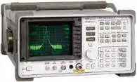
Repair prices
8591E Specifications – click to expand
8591E Specifications
- Portable spectrum analyzer
- Resolution bandwidths to 1 kHz (30 Hz with Option 130 on E-series)
- HP-IB, RS-232 and parallel interfaces available by option
| Specification | Value |
|---|---|
| Frequency range | 9 kHz to 1.8 GHz |
8591E Options – click to expand
8591E Options
- 004, Precision Frequency Reference
- 010, Built-In Tracking Generator
- 021, HP-IB Interface
- 023, RS-232 Interface
- 041, HP-IB and Parallel Interface
- 043, RS-232 and Parallel Interface
- 101, Fast Time-Domain Sweeps
- 105, Time-Gated Spectrum Analysis
- 130, Narrow Resolution Bandwidths
HP / Agilent 8591E Error Messages – click to expand
HP / Agilent 8591E Error Messages
The Agilent 8591E portable spectrum analyzer (9 kHz to 1.8 GHz) reports faults as on-screen messages. Hardware (H) messages point to a failed board; user (U) messages mean a setting or cable issue; (M) messages are information only.
Before anything else: run the self-calibration (CAL FREQ & AMPTD) with CAL OUT cabled to the input and store the results with CAL STORE. Hardware (H) messages that survive a fresh cal mean the 8591E needs service.
8591E notes
- The 8591E uses the A6 YTO and has no YIG-tuned filter, so CAL YTF and preselector messages do not apply.
- With Option 004 (precision frequency reference) the 8591E shows OVEN COLD for the first 5 minutes. That is normal.
- Tracking generator options for the 8591E: Option 010 (50 ohm, 100 kHz to 1.8 GHz) or 011 (75 ohm, 1 MHz to 1.8 GHz).
- The rear-panel 10 MHz REF OUT must be jumpered to EXT REF IN (or an external reference connected), or the 8591E shows REF UNLOCK.
Most common 8591E hardware messages
| Message | Type | Meaning | Likely assemblies |
|---|---|---|---|
| CAL SIGNAL NOT FOUND | U/H | Self-cal could not find the 300 MHz CAL OUT signal (must be within 50 MHz of 300 MHz and above −45 dBm). Check the CAL cable first. With default cal data loaded, the −37 Hz passcode bypasses this check. | A7 analog interface, A9 third converter |
| ADC-2V FAIL | H | At preset the ADC reading of the +2 V reference on the A16 processor/video board is out of limits. Often caused by a bad ±15 V supply or a card-cage board pulling an A16J1 line high. | A8 power supply, A15 motherboard, A16 processor/video, card-cage boards |
| ADC-GND FAIL | H | At preset the ADC ground reading on A16 is out of limits. Same usual suspects as ADC-2V FAIL: ±15 V supplies or a board loading the A16J1 pins. | A7 analog interface, A8 power supply, A15 motherboard, A16 processor/video, card-cage boards |
| REF UNLOCK | M/H | The A9 third converter oscillator is not locked to 10 MHz. Check the rear-panel jumper from 10 MHz REF OUT to EXT REF IN first, then the reference level and cables. | A22 precision reference (Option 004), A25 counter lock, W17/W18 cables |
| SMPLR UNLCK | U/H | Sampling oscillator is not working correctly. Check the external reference connection, then the frequency diagnostics. | A6 YTO, A25 counter lock |
| CAL: GAIN FAIL | H | During CAL AMPTD the signal at the ADC stays too low even with the reference-level DAC at maximum. Trace the signal from the RF input through the IF to the log amp. | A3 input attenuator, A4 first converter, A5 second converter, A6 YTO, A7, A9, A11, A12, A13, A14 |
| CAL: SPAN SENS FAIL | H | Main-coil span calibration failed: it could not find the 0 Hz, 300 MHz and 600 MHz signals in a 750 MHz span. Spurious signals can also cause it. | A6 YTO, A7, A9, A16 |
| USING DEFAULTS: _ _ _ | H | Some memory locations failed their check at power-on. Often a dead memory backup battery. | A16 processor/video (battery) |
| FAIL: xxxx xxxxxxxxxx | H | Power-up circuit test failure on the A16 processor board. See the FAIL code section below. | A16, A7, A17 memory card, A25, card-cage boards |
| FREQ UNCAL | U/H | YTO is more than 20 MHz off the frequency it should be on. Run CAL FREQ and CAL STORE; if it stays, suspect the YTO loop or an unlocked reference/sampler on A25. | A6 YTO, A7 analog interface, A25 counter lock |
Complete 8591E hardware and calibration message list
| Message | Type | Meaning | Likely assemblies |
|---|---|---|---|
| ADC-2V FAIL | H | At preset the ADC reading of the +2 V reference on the A16 processor/video board is out of limits. Often caused by a bad ±15 V supply or a card-cage board pulling an A16J1 line high. | A8 power supply, A15 motherboard, A16 processor/video, card-cage boards |
| ADC-GND FAIL | H | At preset the ADC ground reading on A16 is out of limits. Same usual suspects as ADC-2V FAIL: ±15 V supplies or a board loading the A16J1 pins. | A7 analog interface, A8 power supply, A15 motherboard, A16 processor/video, card-cage boards |
| ADC-TIME FAIL | H | Time between ADC readings is too long. If the unit will not sweep but everything else works, A16 is the likely cause. | A16 processor/video |
| φ LOCK OFF | U/H | YTO is tuning slowly. Normal for a moment during CAL FREQ, preset or a frequency change. If it stays on, run CAL FREQ. | A6 YTO, A9 third converter, A25 counter lock |
| FREQ UNCAL | U/H | YTO is more than 20 MHz off the frequency it should be on. Run CAL FREQ and CAL STORE; if it stays, suspect the YTO loop or an unlocked reference/sampler on A25. | A6 YTO, A7 analog interface, A25 counter lock |
| REF UNLOCK | M/H | The A9 third converter oscillator is not locked to 10 MHz. Check the rear-panel jumper from 10 MHz REF OUT to EXT REF IN first, then the reference level and cables. | A22 precision reference (Option 004), A25 counter lock, W17/W18 cables |
| SMPLR UNLCK | U/H | Sampling oscillator is not working correctly. Check the external reference connection, then the frequency diagnostics. | A6 YTO, A25 counter lock |
| CAL SIGNAL NOT FOUND | U/H | Self-cal could not find the 300 MHz CAL OUT signal (must be within 50 MHz of 300 MHz and above −45 dBm). Check the CAL cable first. With default cal data loaded, the −37 Hz passcode bypasses this check. | A7 analog interface, A9 third converter |
| CAL: GAIN FAIL | H | During CAL AMPTD the signal at the ADC stays too low even with the reference-level DAC at maximum. Trace the signal from the RF input through the IF to the log amp. | A3 input attenuator, A4 first converter, A5 second converter, A6 YTO, A7, A9, A11, A12, A13, A14 |
| CAL: SPAN SENS FAIL | H | Main-coil span calibration failed: it could not find the 0 Hz, 300 MHz and 600 MHz signals in a 750 MHz span. Spurious signals can also cause it. | A6 YTO, A7, A9, A16 |
| CAL: FM SPAN SENS FAIL | H | Could not set the FM coil span sensitivity during CAL FREQ. Run CAL FREQ again. | A6 YTO, A7 analog interface |
| CAL: MAIN COIL SENSE FAIL | H | Could not set the main coil span sensitivity. Load DEFAULT CAL DATA (−37 Hz passcode) and run CAL FREQ again. | A6 YTO, A7 analog interface |
| CAL: ZERO FAIL | H | Could not set the main coil tuning sensitivity. Load DEFAULT CAL DATA and run CAL FREQ again. | A6 YTO, A7 analog interface |
| CAL: RES BW AMPL FAIL | H | During CAL AMPTD a resolution bandwidth filter had more than 2.2 dB loss compared to the 3 kHz filter. The routine stops on the failed bandwidth. | A7, A11/A13 bandwidth filters, A14 log amp |
| CAL: NBW gain / width / 200 Hz notch failed | H | A narrow resolution bandwidth (including 200 Hz) has the wrong gain, width or shape during CAL AMPTD. | A130 narrow RBW board |
| CAL: DATA NOT STORED CAL AMP NEEDED | U/H | You tried to store default cal data. Run CAL FREQ and CAL AMPTD first, then CAL STORE. | A16 processor/video |
| CAL: USING DEFAULT DATA | M | CAL AMPTD did not finish, so default correction factors are in use. | |
| USING DEFAULTS self cal needed | U | Default correction factors are loaded. Run CAL FREQ & AMPTD. | |
| USING DEFAULTS: _ _ _ | H | Some memory locations failed their check at power-on. Often a dead memory backup battery. | A16 processor/video (battery) |
| CAL: cannot execute CALAMP enter: 0 dB PREAMP GAIN | U/H | External preamp gain must be 0 dB before CAL AMPTD. If it is already 0 dB, suspect A16 RAM. | A16 processor/video |
| YTF is not available | U | The 8591E has no YIG-tuned filter, so YTF functions do not apply. | |
| CONF TEST FAIL | U/H | The confidence test failed; another message names the failed check. Connect CAL OUT, run CAL FREQ & AMPTD, and test again. | |
| POS-PK FAIL | H | Confidence test: the positive-peak detector failed. | A16 processor/video |
| SAMPLE FAIL | H | Confidence test: the sample detector failed. | A16 processor/video |
| VID-BW FAIL | H | Confidence test: the video bandwidths are not reducing the noise as they should. | A14 log amp/detector, A16 |
| RES-BW NOISE FAIL | H | Confidence test: the noise floor did not drop when stepping to a narrower resolution bandwidth. Loose IF cover screws can cause it. | A11/A13 bandwidth filters, A7 control lines |
| RES-BW SHAPE FAIL | H | Confidence test: a resolution bandwidth (10 kHz to 3 MHz) is more than 20% off its nominal 3 dB width. | A7, A11/A13 bandwidth filters |
| STEP GAIN/ATTEN FAIL | H | Confidence test: the 10 dB IF step gains did not raise the noise with each reference level step. | A12 amplitude control, A7 control lines |
| FAIL: xxxx xxxxxxxxxx | H | Power-up circuit test failure on the A16 processor board. See the FAIL code section below. | A16, A7, A17 memory card, A25, card-cage boards |
| INVALID SCRMOVE | H | Possible hardware failure. Remove the unit from the bus and preset. | Any internal assembly |
| SYMTAB EMPTY / EMPTY DLP MEM | U | User-defined functions and personalities in memory were deleted. If it shows at every power-up, suspect hardware. | A16 processor/video |
| Memory Overflow: ERASE DLP MEM and reload | U | Too many downloadable programs or user items loaded. Use DISPOSE USER MEM, then reload. | A16 processor/video |
| OVEN COLD | M | Shown for 5 minutes after power-on on units with the Option 004 precision reference. It is a timer only; the oven temperature is not measured. | A22 precision frequency reference |
| TG UNLVL | U/H | Tracking generator unleveled: power set out of range, span beyond the generator range, or bad TG cal data. | A7A1, A24 tracking generator |
| TG SIGNAL NOT FOUND | U | During CAL TRK GEN no signal was seen; check the cable from RF OUT to the input. | A7A1, A24 tracking generator |
| Gate card not calibrated | U/H | Time gating (Option 105) needs CAL AMPTD with nothing connected to GATE TRIGGER INPUT. | A105 gated video board |
| Cannot engage phase lock with current CAL FREQ data | U | Run CAL FREQ before turning on phase lock. | A9 third converter |
| MEAS UNCAL | U | Sweep time, span and bandwidth settings make the measurement uncalibrated. Press AUTO COUPLE, AUTO ALL. | |
| CAL: PASSCODE NEEDED / PASSCODE NEEDED | M/U | The function needs the service passcode (center frequency −37 Hz). |
8591E power-up FAIL codes
A message like FAIL: DF40 0625C1F72D means the 8591E processor (A16) found a circuit fault at power-up or preset. The first 4 hex digits match the 16 LEDs on the edge of A16 and point to the failed circuit. The 10-digit part is three codes: I/O address bus (2 digits), I/O data bus (4 digits) and A16 video RAM (4 digits). Convert each hex digit to binary to find the failed line.
| First 4 digits (bit) | A16 LED | Circuit | A16 part |
|---|---|---|---|
| 1st digit, 8 | 16 | Video RAM | U305, U306 |
| 1st digit, 4 | 15 | I/O bus address | U18 |
| 1st digit, 2 | 14 | CPU | U12 |
| 1st digit, 1 | 13 | 68230 timer/port | U57 |
| 2nd digit, 8 | 12 | I/O bus (odd byte) | U2 |
| 2nd digit, 4 | 11 | I/O bus (even byte) | U3 |
| 2nd digit, 2 / 3rd digit, 8 | 10 / 8 | User RAM | U5 |
| 2nd digit, 1 / 3rd digit, 4 | 9 / 7 | User RAM | U22 |
| 4th digit, 8 | 4 | ROM (odd B) | U6 |
| 4th digit, 4 | 3 | ROM (even B) | U23 |
| 4th digit, 2 | 2 | ROM (odd A) | U7 |
| 4th digit, 1 | 1 | ROM (even A) | U24 |
A video RAM code means the A16 board itself is bad. For I/O bus address or data codes, power down and remove the related boards one at a time; if the code clears, the last board removed is the fault, otherwise suspect A16.
8591E user and setup messages (U)
These mean a setting, cable, card or remote command problem, not a hardware fault.
| Area | Messages |
|---|---|
| Memory card | INVALID CARD, INVALID CARD: BAD MEDIA / DATA ERROR / DIRECTORY / NO CARD / TYPE, No card found, INVALID FILE: NO ROOM, File type incompatible |
| Remote programming | COMMAND ERROR, PARAMETER ERROR, INVALID ITEM, INVALID VALUE PARAMETER, INVALID ENTER FORMAT, INVALID OUTPUT FORMAT, INVALID BLOCK FORMAT: IF STATEMENT, INVALID COMPARE OPERATOR, INVALID REPEAT MEM OVFL, INVALID REPEAT NEST LEVEL, INVALID ACTDEF, INVALID VARDEF, INVALID KEYNAME, INVALID KEYLBL, UNDF KEY, SOFTKEY OVFL |
| Traces, states and files | INVALID SAVE REG, INVALID REGISTER NUMBER, INVALID TRACE, INVALID TRACE NAME, INVALID TRACENAME, INVALID RANGE: Stop < Start, INVALID START INDEX, INVALID STOP INDEX, INVALID STORE DEST, INVALID FILENAME, INVALID <file name> NOT FOUND, INVALID CHECKSUM: USTATE, INVALID WINDOW TYPE, INTERNAL LOCKED, TABLE FULL, No points defined, Trace A is not available, Factory DLP, not adaptable |
| Interface | INVALID HP-IB ADRS/OPERATION, INVALID HP-IB OPERATION REN TRUE, INVALID RS-232 ADRS/OPERATION |
| Measurements | Cannot reach N dB points, Too many signals with valid N dB points, Require 1/3/4 signals > PEAK EXCURSION above THRESHOLD, Signals do not fit expected % AM / TOI pattern, SIGNAL CLIPPED, SETUP ERROR, Marker Count Reduce SPAN, Marker Count Widen RES BW, Stop at marker not available with negative detection, INVALID DET: FM or TV option only, Required option not installed, Function not available in current Mode / with analog display |
| Time gating | Check trigger input, Waiting for gate input, Verify gate trigger input is disconnected before CAL AMPTD |
Need the 8591E fixed? We troubleshoot 8591E YTO, IF, power supply and processor faults to the board and component level and return it calibrated. Free estimate once it arrives; you approve before work starts. Contact us for service.
Message list based on the Agilent 8590 Series Assembly-Level Repair Service Guide (Chapter 14) and the 8590 E-Series and L-Series User's Guide.
HP / Agilent 8591E Replaceable Parts – click to expand
HP 8591E Replaceable Assemblies and Part Numbers
These are the major replaceable assemblies in the HP 8591E, with their HP / Agilent part numbers. Option-specific boards are only present if your 8591E has that option installed. "Exchange" numbers are rebuilt units traded for your old assembly.
| Reference | Assembly | HP part number | Option |
|---|---|---|---|
| A1A1 | Keyboard | 08590-60201 | |
| A1A2 | Rotary Pulse Generator (old style) | 0960-0745 | |
| A1A2 | Rotary Pulse Generator (new style) | 1990-1525 | |
| A1R1 | Volume-Intensity Dual Pot Assembly | 08590-60133 | |
| A2 | Display | 08590-60377 | |
| A3 | Input Attenuator | 0955-0453 | |
| A4 | First Converter | 08590-60214 | |
| A5 | Second Converter | 08590-60117 | |
| A5A1 | Tripler | 08590-60155 | |
| A6 | YIG-Tuned Oscillator (YTO), 2-4 GHz | 0955-0974 | |
| A6A1 | YIG Board | 5062-4888 | |
| A7 | Analog Interface | 08590-60197 | |
| A7A1 | Tracking Generator Control | 08590-60196 | |
| A8 | Power Supply | 5062-8229 | |
| A8 | Power Supply Exchange | 08590-69005 | |
| A9 | Third Converter | 08591-60081 | |
| A9 | Third Converter | 08590-60344 | |
| A9 | Third Converter | 08593-60062 | |
| A11 | Bandwidth Board | 08590-60398 | |
| A12 | Amplitude Control Board | 08590-60105 | |
| A13 | Bandwidth Board | 08590-60398 | |
| A14 | Log Amplifier Board | 08590-60386 | |
| A15 | Motherboard | 08591-60062 | |
| A16 | Processor Board | 08590-60416 | |
| A16A1 | 2X Memory Board | 08590-60399 | |
| A16A1BT1 | Battery | 1420-0394 | |
| A17 | Memory Card | 08590-60396 | |
| A22 | 10 MHz Reference | 08591-60048 | Option 704 |
| A22 | 10 MHz Precision Frequency Reference | 1813-0644 | Option 004 |
| A24A1 | Tripler | 5086-7807 | |
| A24A2 | Tracking Converter | 08590-60146 | |
| A24A3 | Amplifier/Detector | 5086-7808 | |
| A24A4 | Output Attenuator | 0955-0453 | |
| A24FL1 | Low-Pass Filter | 0955-0491 | |
| A25 | Counter Lock Board | 08591-60098 | |
| A25A1 | Sampler Assembly | 5086-7806 | |
| A40 | IB and Parallel Interface Board | 08590-60366 | Option 041 |
| A40A1 | IB and Parallel Interface Connector | 08590-60368 | Option 041 |
| A41 | RS-232 and Parallel Interface Board | 08590-60366 | Option 043 |
| A41A1 | RS-232 and Parallel Interface Connector | 08590-60369 | Option 043 |
| A41/A43 | Dual I/O Board | 08590-60366 | Option 041, Option 043 |
| A101 | Fast ADC Board | 5062-7079 | Option 101 |
| A102 | Demod/TV-Sync Board | 5062-1982 | Option 102 |
| A103 | Demod/QPD Board | 5062-1983 | Option 103 |
| A105 | Gated Video Board | 5062-7754 | Option 105 |
| A110 | Cellular Demod/TV Board | 5063-0234 | Option 110 |
| A119 | Noise Card Board | 5062-8258 | Option 119 |
| A130 | Narrow Bandwidth Board | 08590-60352 | Option 130 |
| A151 | Down Converter Assembly | 5062-8246 | Option 151 |
| A160 | DSP Assembly (without firmware) | 5062-8245 | Option 160 |
| A160 | DSP Assembly (with firmware) | 08591-60101 | Option 160 |
| A163 | DSP Assembly (GSM/DCS Formats) (with firmware) | 5062-0577 | Option 163 |
| AT2 | 50 Ohm Termination | 0960-0053 | |
| B1 | Fan (includes cable assembly) | 5063-0243 | |
| F1 | Fuse 5.0 A 250 V F | 2110-0709 | |
| FL1 | Low-Pass Filter 4.9 GHz | 9135-0048 | |
| J1 | Input 50 Ω | 1250-2191 | |
| J1 | Input 75 Ω (MLA) | 0955-1005 | Option 001 |
| J3 | RF OUT 50 Ω | 1250-2191 | Option 010 |
| J3 | RF OUT 75 Ω (MLA) | 0955-1005 | Option 011 |
Part obsolete or unavailable? Many 8591E assemblies are no longer sold by Keysight. Analyzer Repair Inc. repairs these boards and modules at the component level in Cocoa, Florida. Free estimate once the unit is in our lab. Contact us for service.
From the Agilent 8590 Series Analyzers Assembly-Level Repair Service Guide (08590-90316), Table 12-5.