
Keysight (Agilent HP) 8566B Repair Service
Product model
8566B spectrum analyzer 100Hz-22GHzServices
Need your HP 8566B Spectrum Analyzer repaired or calibrated? Our veteran-owned lab handles both, with free estimates and quick turnaround.
Description
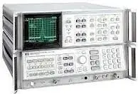
The Agilent 8566B, 8567A, and 8568B are high-performance spectrum analyzers for bench and ATE system use. The Agilent 8566B has the highest performance of the three, with a frequency range from 100 Hz to 22 GHz that can be extended to 325 GHz using external mixers. The Agilent 8567A and 8568B are RF spectrum analyzers with frequency coverage to 1500 MHz..
Repair prices
8566B Specifications – click to expand
8566B Specifications
- The exceptional frequency stability of the Agilent 8566B and the Agilent 8568B makes it possible to make measurements with a 10 Hz resolution bandwidth
- This narrow resolution bandwidth yields sensitivities to -135 dBm in both instruments
- Excellent frequency stability, sensitivity, and frequency-reference accuracy combine to allow very accurate measurement of small signals in the presence of large ones
8566B Options – click to expand
8566B Options
- 400 - 400 Hz Power Line Frequency operation
- 907 - Front Handle Kit
- 908 - Rack Flange Kit
- 909 - Rack Flange and Handle Kit
- 910 - Extra Manual
HP 8566B Error Messages and Unlock Codes – click to expand
HP 8566B Error Messages
The HP 8566B (100 Hz to 22 GHz) does not use numbered error codes. Instead it shows up to eleven special messages in the upper-right corner of the CRT. Some are just operator information; the unlock messages mean a phase-lock loop has failed and the 8566B needs repair.
8566B unlock messages (hardware faults)
| Message | Meaning | Assemblies to check |
|---|---|---|
| YTO UNLOCK | The YTO phase-lock loop is unlocked. | A19 D/A converter, A20 main coil driver, A21 FM coil driver, A11 YTO loop, A16 scan generator |
| PL1 UNLOCK | Phase lock loop 1 (20/30 synthesizer) is unlocked. | A10A1 through A10A4 |
| PL2 UNLOCK | Phase lock loop 2 is unlocked. | A10A5 through A10A8 |
| REF UNLOCK | The 10 MHz reference loop is unlocked. Normal while OVEN COLD is showing. Otherwise check the rear-panel W15 jumper and the EXT/INT reference switch. | A7A1, A7A2, A22 frequency standard |
| M/N UNLOCK | The M/N phase-lock loop is unlocked. | A7A3, A7A4 |
| HET UNLOCK | The RF module (heterodyne) phase-lock loop is unlocked. | A6A9 phase lock, A6A4 second converter (3.3 GHz) |
When more than one unlock message shows
One failed loop often unlocks others. Use the combination to find the real fault:
| Messages shown | Most likely failed loop | Assemblies |
|---|---|---|
| PL1 + PL2 | Loop 2 | A10A5 to A10A8 |
| PL1 + YTO | Loop 1 | A10A1 to A10A4 |
| PL1 + PL2 + YTO | Loop 2 | A10A5 to A10A8 |
| REF + PL1 + PL2 | Reference loop | A7A1, A7A2, A22 |
| REF + M/N + YTO | Reference loop | A7A1, A7A2, A22 |
| M/N + YTO | M/N loop | A7A3, A7A4 |
| HET + REF | Reference loop | A7A1, A7A2, A22 |
| All unlock messages at once | 100 MHz VCXO | A7A2 |
8566B information messages
| Message | Meaning |
|---|---|
| OVEN COLD | The frequency reference oven is still warming up. Normal for about 10 minutes after power is first applied; it stays warm in STANDBY. |
| BATTERY | Shown only at turn-on: the CMOS memory on the A15 controller lost its stored states, so all states were reset to preset and the HP-IB address was lost. Points to the A15 memory backup supply or battery. A "long POP" check also clears memory and causes this message. |
| MEAS UNCAL | Sweep is too fast for the selected bandwidth, so the displayed data is not valid. Slow the sweep or use auto-coupled settings. |
| Trace not updated | Settings were changed but the displayed trace has not been updated (for example, trace A in VIEW and the center frequency changed). |
| EXT REF | The external frequency reference is selected. |
| SRQ 110 / SRQ 140 | Service requests: 110 = hardware broken, 140 = illegal command received over HP-IB. |
Self-check: the 8566B internal error correction routine (SHIFT, FREQUENCY SPAN) and its data display help separate amplitude and frequency faults. If "Adjust AMPTD CAL" appears, repeat the CAL adjustment before running it.
Unlock message on your 8566B? Analyzer Repair Inc. repairs HP 8566B RF and IF sections in-house in Cocoa, Florida, including synthesizer, YTO and reference loop faults. Free estimate once the unit is in our lab. Contact us for service.
Based on the HP 85660B RF Section Troubleshooting and Repair Manual (85660-90210), Overall and Analog Troubleshooting.
HP 8566B Replaceable Parts – RF Section (85660B) – click to expand
HP 8566B RF Section Replaceable Assemblies
Assembly-level HP/Agilent part numbers for the HP 85660B RF section of the HP 8566B spectrum analyzer. Where more than one number is listed, the assembly changed by serial prefix or was replaced by a newer part; check your unit's serial prefix before ordering. Many of these parts are obsolete at Keysight.
| Reference | Assembly | HP part number(s) |
|---|---|---|
| A5 | Front Panel Assembly | 85660-60232, 85660-60258 |
| A5A1 | Keyboard Assembly | 85660-60210 |
| A5A2 | Rotary Pulse Generator | 5060-0329 |
| A6A1 | RF Switch | 85660-60101, 3106-0029 |
| A6A2 | RF Attenuator/Error Correction ROM | 85660-60336, 85660-60304, 85660-60121 |
| A6A3 | Last Converter Assembly | 85660-60003 |
| A6A3A1 | Last Converter Board Assembly | 85660-60002 |
| A6A5 | Amplifier/Coupler/Load Unit (ACLU) | 5086-7133 |
| A6A6 | First Converter | 5086-7247 |
| A6A7 | Board Assembly, YIG-Tuned Mixer Current | 85660-60128 |
| A6A8 | YIG-Tuned Mixer (YTX) | 5086-7226, 5086-6226 |
| A6A9 | Phase Lock Assembly | 85660-60226, 85660-60256 |
| A6A9A1 | Phase Lock Board Assembly | 85660-60253, 85660-60202 |
| A6A10 | Board Assembly, Misc. Bias/Relay Driver | 85660-60322, 85660-60180 |
| A6A11 | Board Assembly, Slope Generator | 85660-60238, 85660-60126 |
| A6A12 | Board Assembly, YIG-Tuned Mixer (YTX) Drive | 85660-60013, 85660-60235, 85660-60366 |
| A6A13 | Board Assembly, RF Module Motherboard | 85660-60014 |
| A7A1 | Board Assembly, Reference Phase Detector | 85660-60015 |
| A7A2 | Board Assembly, 100 MHz VCXO | 85660-60135 |
| A7A3 | Board Assembly, M/N Phase Detector | 85660-60136 |
| A7A4 | M/N Output Assembly | 85660-60113, 85660-60267 |
| A7A4A1 | M/N Voltage Controlled Oscillator | 85660-60096 |
| A7A4A1A1 | M/N Voltage Controlled Oscillator | 85660-60112 |
| A7A4A1A2 | M/N VCO Board Assembly | 85660-60018 |
| A7A4A2 | M/N Output Board Assembly | 85660-60192, 85660-60266, 85660-60239 |
| A7A5 | Reference Motherboard | 85660-60020 |
| A8 | Rectifier Board Assembly | 85660-60196 |
| A10A1 | Board Assembly, PLL1 VCO | 85660-60131 |
| A10A3 | Board Assembly, PLL 1 If | 85660-60024 |
| A10A4 | Board Assembly, PLL 3 Up Converter | 85660-60025 |
| A10A5 | Board Assembly, PLL2 VCO | 85660-60168 |
| A10A6 | Board Assembly, PLL Phase Detector | 85660-60130, 85660-60229, 85660-60276 |
| A12 | Board Assembly, Front Panel Interface | 85660-60246, 85660-60290 |
| A15 | Board Assembly, Controller | 85660-60209, 85660-60245 |
| A16 | Board Assembly, Scan Generator | 85660-60198, 85660-60247 |
| A17 | Board Assembly, Positive Regulator | 85660-60174, 85660-60323 |
| A18 | Board Assembly, Negative Regulator | 85660-60137 |
| A19 | Board Assembly, Digital-To-Analog | 85660-60212 |
| A20 | Board Assembly, Main Coil Driver | 85660-60206 |
| A21 | Board Assembly, Fm Coil Driver | 85660-60040 |
| A22 | 10 MHz Frequency Standard Assembly | 5062-1916, 85660-60046 |
| A22A1 | Board Assembly, 10 MHz Frequency | 5062-1909, 5062-4837 |
| A23 | Board Assembly, Motherboard | 85660-60041, 85660-60368 |
Can't find a part? Analyzer Repair Inc. repairs 8566B assemblies at the component level, which is often the only option for obsolete boards. Free estimate once the unit is in our lab. Contact us for service.
From the HP 85660B RF Section Troubleshooting and Repair Manual (85660-90210). IF-display section (85662A) parts not included.