Repair and Calibration Services
E5052B
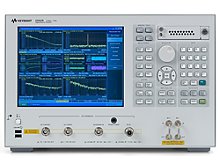
E5052B Signal Source Analyzer
Our full capability facility can repair and calibrate your Agilent E5052B Signal Source Analyzer. We specialize in servicing obsolete, unsupported test equipment.

Description:
The E5052B 10 MHz to 7 GHz Signal Source Analyzer features a number of enhanced performance characteristics, partially shown in the key features above. And it offers world's highest measurement throughput and best usability in characterizing VCO or other types of high frequency signal sources, as well as clock jitter evaluation in high-speed data communication systems.
Specifications:
RF IN connector Type-N (female), 50 Ω nominal
RF IN frequency range 10 MHz to 7 GHz
RF IN measurement level -20 dBm to +20 dBm (> 30 MHz)
-15 dBm to +20 dBm (< 30 MHz)
Input attenuator 0 to 35 dB (in 5 dB step)
Input damage level AC> +23 dBm, DC> 5V
Input VSWR @50 Ω
10 MHz to 30 MHz < 1.6
30 MHz to 2 GHz < 1.2
2 GHz to 3 GHz < 1.3
3 GHz to 4 GHz < 1.3 typical
4 GHz to 7 GHz < 1.5 typical
Options:
RF IN frequency range 10 MHz to 7 GHz
Measurement frequency bands 10 MHz to 41 MHz, 39 MHz to 101 MHz,
99 MHz to 1.5 GHz, 250 MHz to 7 GHz1
RF frequency tracking range 0.4% of carrier frequency
Measurement parameters
SSB phase noise [dBc/Hz], Spurious noise [dBc],
Integrated rms phase deviation [deg, rad] or time jitter [s],
Residual FM [Hz rms]
Number of trace 1 data trace and 1 memory trace with ‘data math’ functions
Measurement trigger continuous/single/hold source: internal/external/manual/bus
Offset frequency range (effective)
RF carrier signal> 1 GHz
(> 400 MHz for wide capture mode)
1 Hz to 100 MHz
1 Hz to 40 MHz (wide capture mode)
10 Hz to 100 MHz
10 Hz to 40 MHz (wide capture mode)
RF carrier signal < 1 GHz
(< 400 MHz for wide capture mode) 1 Hz to 10% of carrier frequency 10 Hz to 10% of carrier frequency
Documents:
Located in: Keysight (Agilent HP)
